
A floating turbidity barrier consists of geotextile material (curtain) which floats on the top, weighted on the bottom, and an anchorage system that minimizes the sediment transport from a disturbed area that is adjacent to or within a body of water. The barrier provides sedimentation and turbidity protection for a watercourse for up-slope land-disturbance activities where conventional erosion and sediment controls cannot be used or need supplemental sediment control, or from dredging or filling operations within a watercourse. The practice can be used in non-tidal and tidal watercourses where intrusion into the watercourse by construction activities has been permitted and subsequent sediment movement is unavoidable.
Planning Considerations
Soil loss into a watercourse results in long-term suspension of sediment. In time, the suspended sediment may travel long distances and affect widespread areas. A turbidity barrier is designed to deflect and contain sediment within a limited area and provide enough residence time so that soil particles will fall out of suspension and not travel to other areas.
Turbidity barrier types must be selected based on the flow conditions within the waterbody, whether it is a flowing channel, lake, pond, or a tidal watercourse. The specifications contained within this practice pertain to minimal- and moderate- flow conditions where the velocity of flow may reach 5 ft. /sec (or a current of approximately 3- knots). For situations where there are greater flow velocities or currents, a qualified design professional and the product manufacturer should be consulted.
Consideration must also be given to the direction of water movement in channel-flow situations. Turbidity barriers are not designed to act as water impoundment dams and cannot be expected to stop the flow of a significant volume of water. They are designed and installed to trap sediment; not to halt the movement of water itself. In most situations, turbidity barriers should not be installed across channel flows. There is an exception to this rule. This occurs when there is a danger of creating a sediment buildup in the middle of a watercourse, thereby blocking access or creating a sediment bar. Curtains have been used effectively in large areas of moving water by forming a very long-sided, sharp “V” to deflect clean water around a work site, confining a large part of the sediment- laden water to the work area in the “V” and directing much of the sediment toward the shoreline. Care must be taken, however, not to install the curtain perpendicular to the water current.
In tidal or moving water conditions, provisions must be made to allow the volume of water contained within the barrier to change. Since the bottom of the barrier is weighted and external anchors are frequently added, the volume of water contained within the curtain will be much greater at high tide versus low tide, and measures must be taken to prevent the curtain from submerging. In addition to allowing slack in the curtain to rise and fall, water must be allowed to flow through the curtain if the curtain is to remain roughly the same place and maintain the same shape. Normally, this is achieved by constructing part of the curtain from a heavy, woven filter fabric. The fabric allows the water to pass through the curtain, but retains the sediment particles. Consideration should be given to the volume of the water that must pass through the fabric and the sediment particle size when specifying fabric permeability.
Sediment which has been deflected and settled out by the curtain, may be removed if so directed by the on-site inspector or the permitting agency. However, consideration must be given to the probable outcome of the procedure, which may create more of a sediment problem by re-suspension of the particles and accidental dumping of the material by the equipment involved. It is, therefore, recommended that the soil particles trapped by a turbidity curtain be removed only if there has been a significant change in the original contours of the affected area in the watercourse. Regardless of the decision made, soil particles should always be allowed to settle for a minimum of 6-12 hours before removal by equipment or before removal of a turbidity curtain.
It is imperative that all measures in the erosion- control plan be used to keep sediment out of the watercourse. However, when proximity to the watercourse makes successfully mitigating sediment loss impossible, the use of turbidity curtain during land disturbance is essential. Under no circumstances should permitted land- disturbing activities create violations of water quality standards.
Design Criteria and Construction
Floating turbidity barriers are normally classified into three types:
- Type 1 (see Figure TB-1) is used in protected areas where there is no current and the area is sheltered from wind and waves.
- Type 2 (see Figure TB-2) is used in areas where there may be small to moderate current (up to 2 knots or 3.5ft/sec) and or wind and wave action can affect the curtain.
- Type 3 (see figure TB-3) is used in areas where considerable current (up to 3 knots or 5 ft. /sec) may be present, where tidal action may be present, and/or where the curtain is potentially subject to wind and wave action.
Turbidity barriers should extend the entire depth of the watercourse whenever the watercourse in question is subject to tidal action and/or significant wind and wave forces. This prevents sediment-laden water from escaping under the barrier, scouring, and re-suspending additional sediments.
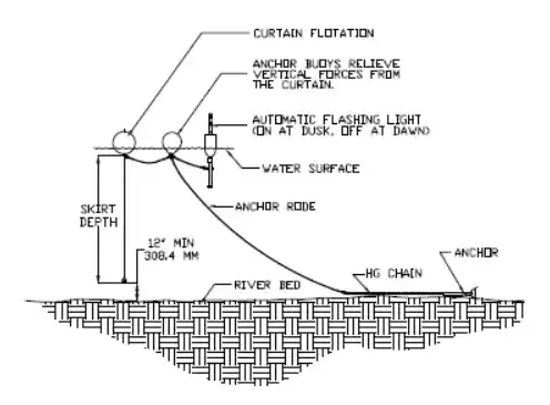
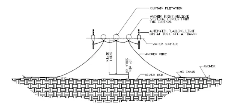
In tidal and/or wind- and wave- action situations, the curtain should never be so long as to touch the bottom. A minimum of 1- foot gap should exist between the weighted, lower end of the skirt and the bottom at “mean” low water. Movement of the lower skirt over the bottom due to tidal reverses or wind and wave action on the floatation system may fan and stir sediments already settled out.
In tidal and/or wind- and – wave action situations, it is seldom practical to extend a turbidity curtain depth lower than 10 to 12 feet below the surface, even in deep water.
Curtains that are installed deeper than this will be subjected to very large loads with consequent strain on curtain materials and the mooring system. In addition, a curtain installed in such a manner can “billow up” toward the surface under the pressure of the moving water, which will result in an effective depth that is significantly less than the skirt depth.
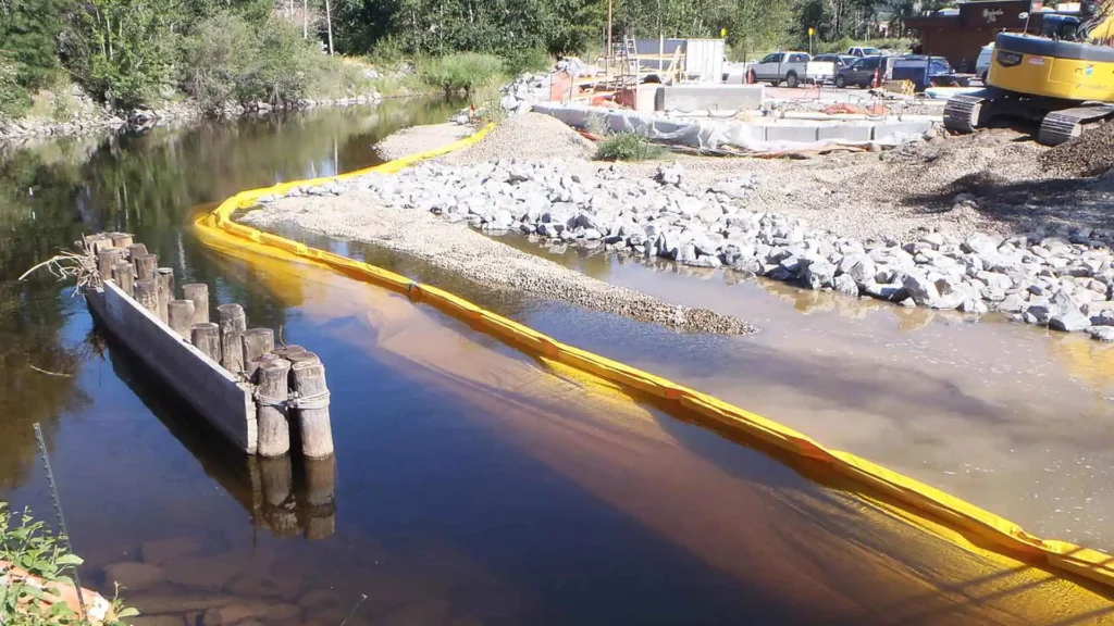
Turbidity curtains should be located parallel to the direction of flow of a moving body of water. Turbidity curtains should not be placed across the main flow of a significant body of moving water.
When sizing the length of the floating curtain, allow an additional 10-20% variance in the straight- line measurements. This will allow for measuring errors, make installation easier and reduce stress from potential wave action during high winds.
An attempt should be made to avoid an excessive number of joints in the curtain. A minimum continuous span of 50 feet between joints is a good “rule of thumb”.
For stability reasons, a maximum span of 100 feet between anchor or stake locations is also a good rule to follow.
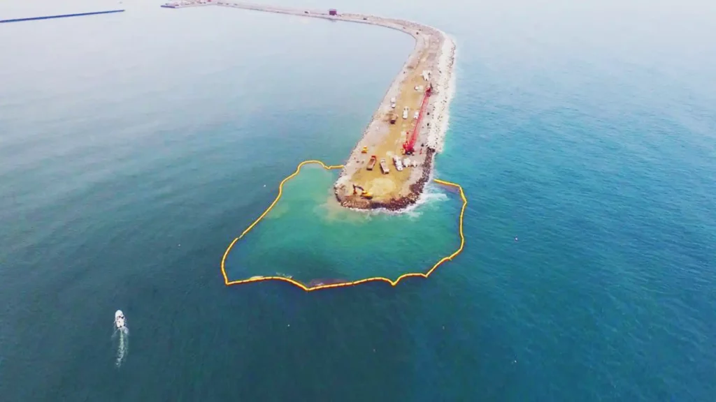
The end of the curtain, both floating upper and weighted lower, should extend well up onto the shoreline, especially if high water conditions are expected. The ends should be secured firmly to the shoreline to fully enclose the area where sediment may enter the water.
When there is a specific need to extend the curtain to the bottom of the watercourse in tidal or moving water conditions, a heavy, woven, pervious filter fabric may be substituted for the normally recommended impervious geotextile. This creates a “flow-through” medium, which significantly reduces the pressure on the curtain and will help to keep it in the same relative location and shape during the rise and fall of tidal waters.
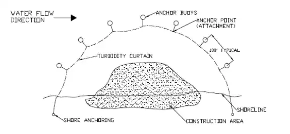
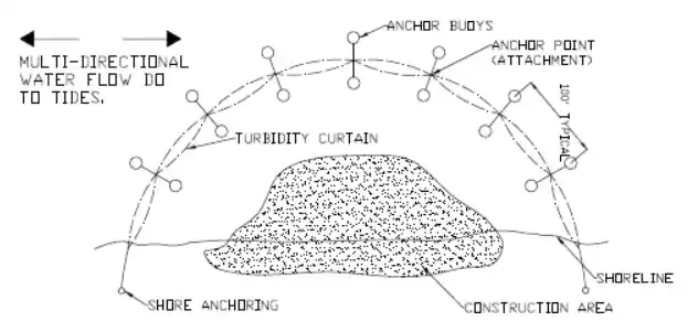
Typical installation layouts of turbidity curtains can be seen in Figure TB-4. The number and spacing of external anchors will vary depending on current velocities and potential wind and wave action. Manufacturer’s recommendations should be followed.

In navigable waters, additional permits may be required from the U.S. Army Corps of Engineers or other regulatory agencies if the barrier creates an obstruction to navigation.
Site Preparation
If a floating turbidity barrier is specified in the erosion and sediment control plan, it should be installed before any land-disturbing activities. Shoreline anchor points should be located according to the plan.
Materials and Installation
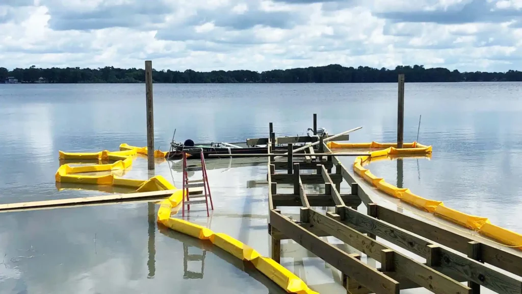
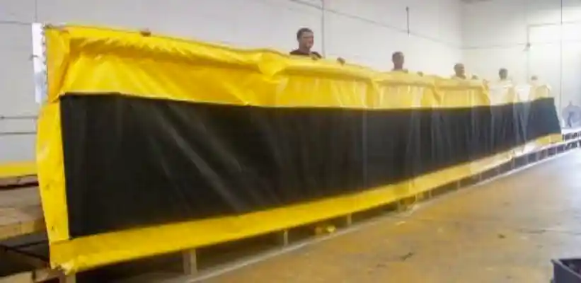
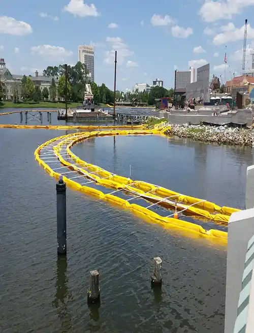
Barriers should be a bright color (yellow or “international” orange) that will attract the attention of nearby boaters. The curtain fabric must meet the minimum requirements noted in job specifications.
When installing type I barrier in the calm water of lakes or ponds, it is usually sufficient to merely set the curtain end stakes or anchor points (using anchor buoys if bottom anchors are employed); then, tow the curtain in the furled condition out and attach it to these stakes or anchor points. Following this, any additional stakes or buoyed anchors required to maintain the desired location of the curtain may be set, and these anchor point made fast to the curtain. Only then, the furling lines should be cut to let the skirt drop.
When installing Type 2 or Type 3 barriers in rivers or in other moving water, it is important to set all the curtain points. Care must be taken to ensure that the anchor point is of sufficient holding power to retain the curtain under the expected current condition, before putting the furled curtain into the water. Anchor buoys should be employed on all anchors to prevent the current from submerging the floatation at the anchor points. If the moving water into which the curtain is being installed is tidal and will subject the curtain to currents in both directions as the tide changes, it is important to provide anchors on both sides of the curtain for two reasons:
- Curtain movement will be minimized during tidal current reversals.
- The curtain will not overrun the anchors, pulling them out when the tide reverses.
When the anchors are secure, the furled curtain should be secured to the upstream anchor point and then sequentially attached to each next downstream anchor point until the entire curtain is in position. At this point, and before furling, the “lay” of the curtain should be assessed and any necessary adjustments made to the anchors. Finally, when the location is ascertained to be as desired, the furling lines should be cut to allow the skirt to drop.
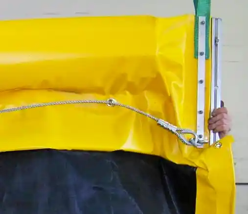
The anchoring line attached to the floatation device on the downstream side will provide support for the curtain. Attaching the anchors to the bottom of the curtain could cause premature failure of the curtain due to the stresses imparted on the middle section of the curtain.
Seams in the fabric should be either vulcanized welded or sewn, and should develop the full strength of the fabric.
Flotation devices should be flexible, buoyant units contained in an individual flotation sleeve or collar attached to the curtain. Buoyancy provided by the flotation units should be sufficient to support the weight of the curtain and maintain a freeboard of at least 3” above the water surface level.
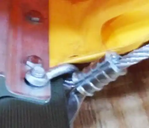
Load lines must be fabricated into the bottom of all floating turbidity curtains. Type 2 and Type 3 curtains must have load lines also fabricated into the top of the fabric. The top load line must consist of woven webbing or vinyl-sheathed steel cable and should have break strength in excess of 10,000 pounds (5 t). The supplemental (bottom) load line should consist of a chain incorporated into the bottom hem of the curtain sufficient weight to serve a ballast to hold the curtain in a vertical position. Additional anchorage should be provided as necessary. The load lines should have suitable connecting devices that develop the full breaking strength for connection to load lines in adjacent sections.
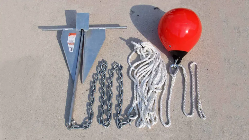
External anchors may consist of 2”x 4” or 2 1/2” minimum diameter wooden stakes, or 1.33 pounds/linear foot steel post when Type I installation is used. When Type II or Type II installations are used, bottom anchors should be used.
Bottom anchors must be sufficient to hold the curtain in the same position relative to the bottom of the watercourse without interfering with the action of the curtain. The anchor may dig into the bottom (grappling hook, plow or fluke- types) or may be weighted (mushroom type) and should be attached to a floating anchor buoy via an anchor line. The anchor line would then run from the buoy to the top load line of the curtain. When used with Type III installations, these lines must contain enough slack to allow the buoy and the curtain to float freely with tidal changes without pulling the buoy or curtain down and must be checked regularly to make sure they do not become entangles with debris. As previously note, anchor spacing will vary with current and velocity and expected wind and wave action. Manufacturer’s recommendations should be followed.
Installing two parallel curtains, separated at regular intervals by 10 feet long wooden boards or lengths of pipe can increase the effectiveness of the barrier.
Construction Verification
Check the type of turbidity barrier, installation location, and the installation and anchorage procedures for compliance with the standard drawings and materials list.
(Check for compliance with specifications if included in contract specifications)
Removal
Care should be taken to protect the skirt from damage as the turbidity curtain is dragged from the water.
The site selected to bring the curtain ashore should be free of sharp rocks, broken cement, debris, ect., as to minimize damage when hauling the curtain over the area.
If the curtain has a deep skirt, it can be further protected by running a small boat along its length with a crew installing furling lines before attempting to remove the curtain from the water.
Common Problems
Consult with a qualified design professional if any of the following occurs:
- Variations in topography on site indicate that the floating turbidity barrier will not function as intended.
- The specified anchorage system will not function as planned.
- Turbidity water is escaping from the barrier enclosure.
- Materials specified in the plan are not available.
Maintenance
The floating turbidity barrier should be maintained for the duration of the project to ensure the continuous protection of the watercourse. Anchors, anchor lines and buoys must be regularly checked for debris.
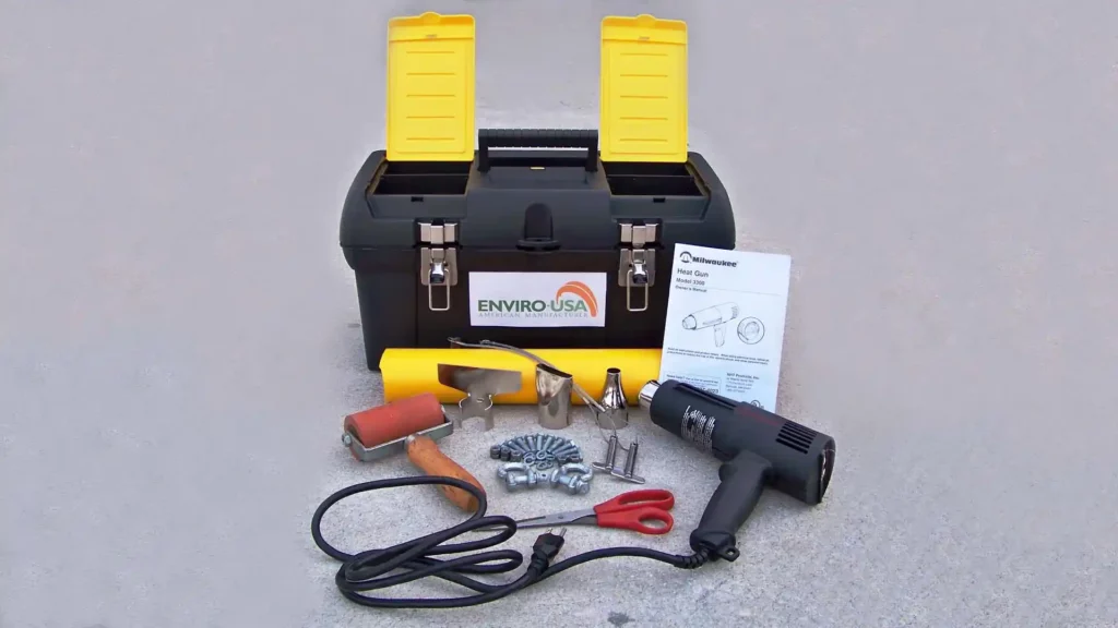
If repairs to the geotextile become necessary, normally repair kits are available from the manufacturer. Follow the manufacturer’s instructions to ensure the adequacy of the repair.
When the curtain is no longer required as determined by the responsible individual, the curtain and related components should be removed in such a manner as to minimize turbidity. If required by the contract or the responsible individual, sediment should be removed, and the original depth (or plan evaluation) restored before removing the curtain. Remaining sediment should be sufficiently settled before removing the curtain. Any spoils should be taken to an upland area and stabilized.